This article provides a comparative analysis of devices for remote detection of methane leaks. Particular attention is paid to various types of scanning systems and methods for increasing their sensitivity. The results of experimental studies aimed at detecting methane leaks with low concentrations are presented, emphasizing the relevance and practical significance of the work.
By Johan Wictor, Carlos Grijalba Arroyo, Mihai Pelsa, Oleg Ershov, Alexey Klimov, Svyatoslav Kudryavstev & Semen Neverov – Pergam Group (Italy, Switzerland, USA)
** This is part one of a two part series **
The oil and gas industry is a significant contributor to methane emissions.1 Most methane leaks occur during gas transportation and storage in underground storage facilities.2
Since inspections must be carried out at least twice a year – in the spring and autumn (the period of soil movement) – it is necessary to use technologies that will allow the fastest and most effective monitoring of the condition of gas pipelines and the identification of natural gas leaks.

Pergam Group has developed and manufactured portable remote gas detectors ALMA (Airborne Leak Methane Assessment) since 2004. They have been used for remote inspections of pipelines – from helicopters and other aircrafts – worldwide for 20 years. Development of ALMA has continued, seeking to improve operation, its usability, and the convenience of its data presentation, and more. ALMA Generation 4 (G4) has been used for inspection work since 2018, and was used during the helicopter field test described below. The main goal of this field test was to confirm detection of artificial methane leak with gas flow rate 17 g/hour, which is accepted as the detection limit for inspections of pipelines in the European Union by airborne gas detectors.
Review of Solutions and Instrument Operation
Oil and gas pipelines are long and have many branches. The corridor width ranges from 10 to 30 meters, so a device is needed that can scan the territory from a maneuverable air carrier. Helicopters and helicopter-type unmanned aerial vehicles (UAVs) are suitable for this. Modern developments in oil and gas pipeline methane detection systems are explored below.

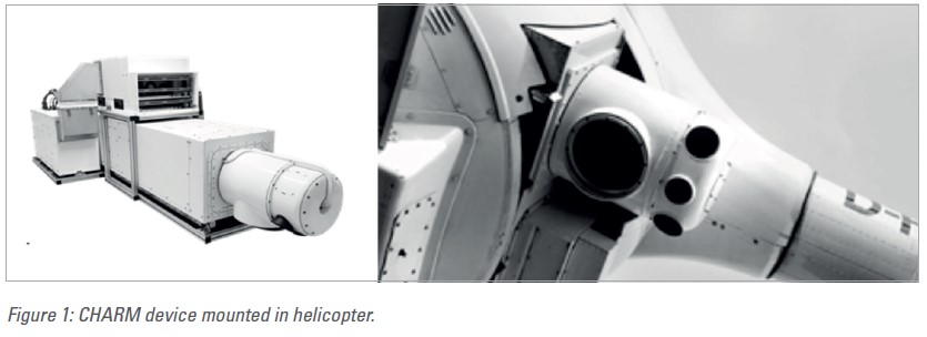
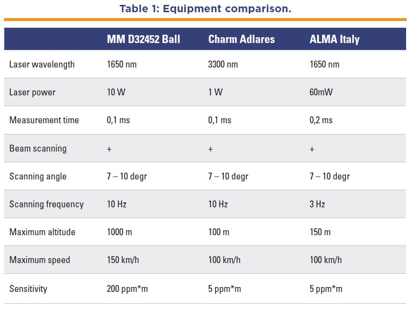
CHARM is a helicopter-mounted infrared airborne lidar. The German instrument was jointly developed by DLR, Adlares GmbH and E. ON Ruhrgas AG. CHARM is based on the DIAL (Differential Absorption Lidar) principle, an established active remote sensing method for detecting various gases in the atmosphere. The CHARM system is designed as a monostatic configuration using a 150 mm Newtonian telescope. Typically, an 18m wide strip is covered with measurement points distributed evenly across the width of the pipeline corridor.
MM D32452 technology uses wavelength modulation spectroscopy at 1651 nm to measure path-integrated methane concentrations between theaircraft and the ground, acting as a topographic backscatter. Forward and back measurements during the aircraft flight provide information on the detected plume height, typically with an accuracy of 2m.
The operation of ALMA technology is based on the absorption of light by methane molecules at a wavelength range close to 1650 nm. A diode laser with an amplifier is applied in ALMA as a source of light. The output last is about 60 nW. The laser beam of the airborne ALMA hits the surface of the ground so that laser light is scattered by topographic objects. A small portion of the scattered laser beam is reflected and captured by the optics of ALMA for subsequent processing in its computer online program. The output is the current methane concentration.
The ALMA laser continuously emits short pulses with a duration of 0.2 msec. The wavelength is scanned in each laser pulse, near the methane absorption line, so that the line is positioned exactly in the center of each pulse. Calculation of the absorption in each signal pulse allows for the measurement of methane concentration in the laser beam. The results of the measurement are averaged over 200 pulses, so the measurement time of the instrument equals 40 msec. ALMA simultaneously measures the distance to target for the subtraction of atmospheric methane, equaling 1.8 ppm for each meter of distance.
The detection limit of measurement sensitivity depends on the distance to the target. The detection limit or measurement sensitivity depends on the distance to the target. The best sensitivity (5 ppm*m) is achieved with the aircraft at an altitude of 25-50 meters (note that subtracted atmospheric methane at an altitude of 50 meters equals 90 ppm*m). ALMA G4 is capable of detecting methane at altitudes up to 150 meters, wherein measurement sensitivity equals 100 ppm*m. The diameter of the laser beam spot equals 1m at an altitude of 75m and 2m at an altitude of 150m.
During the comparison, several characteristics were revealed that limit of scope of the application for these systems. Scanning of a laser beam with a frequency of 10 Hz is possible only when using a compact receiving system with a diameter of no more than 4cm, and a laser power of more than 10 W. Stability of the laser power is one of the key factors limiting the sensitivity of measurements. The MM D32452 and CHARM devices are not compact – they have a fairly large weight (from 220 to 350 kg) and dimensions and must be installed on a fairly large aircraft. The scanning band of these devices is 30m at a flight altitude of 100m.
In terms of measurement sensitivity, the BALL device is significantly inferior to the CHAR< device, but it can be used to take measurements in a wide band from an altitude of 1km. The CHARM device cannot be used at altitudes above 100m due to the saturation of absorption by atmospheric methane at an altitude of 1km is 1800 ppm*m.

After analyzing the equipment and collecting data from oil and gas competitors – the consumers of this equipment – the following detection parameters for the equipment were identified:
- Equipment operating range – more
than 60m
- Detection sensitivity – from 5
ppm*m
- Scanning area – more than 25 meters
- Scanning resolution – a flight altitude
of 100m-1m2
- Possibility of installing the equipment
on various carriers
In order to reduce the mass and size of the device, the data processing boards were upgraded and the design of the device was redesigned, making it possible to produce a single-block device with a mass of 6.2 kg. Figure 2 shows the appearance of the device before (1-3) and after (4-5) modernization.
Scanning is a separate task. It is necessary to place a rotating optical element in the laser beam that redirects the laser radiation at a certain angle. Such an element can be a glass prism, an element consisting of three flat mirrors in the form of an equilateral triangle, an element consisting of four flat mirrors in the form of a square, and more. Since the laser beam upon exit of the device has a transverse size of less than 1cm, the scanning optical element is very compact.
This makes it easy to rotate at a speed of up to 5 revolutions per second, which is sufficient for the purpose of the scanning system. However, the operation of the remote laser detector requires that the reflected (scattered) laser beam hit the photodetector at all positions of the laser spot on the earth’s surface. This makes necessary the design of the rotating optical element. A symmetrical piece that receives the reflected beam is added to the rotating element. The optics are calculated in such a way that the received beam is about 1cm, which is not a problem for devices with a powerful laser.
To reduce the noise characteristic, it is necessary to reduce the background heterogeneity. This can be achieved by increasing the diameter of the laser radiation spot. Since the energy of the DFB laser is low, it is also necessary to increase the aperture. When increasing the aperture of the input channel, a problem arises with the development of the scanning system.
Stay tuned for Part Two of this article in the December issue of Fugitive Emissions Journal.


