By Howard Williams, Business Development Manager, Bray International
Today, news regularly focuses on the effects of global warming on our environment, including the considerable methane emissions from traditionally controlled gas pipeline valves. Availability of an alternative clean energy source is therefore highly desirable, so the existing pipeline networks can be properly retrofitted.
How Gas Powered Pipeline Valve Actuators Work
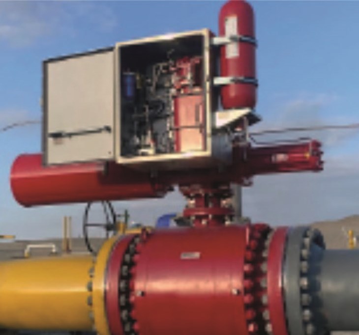
The gas pressure in the pipeline is used to power either a linear cylinder (thrust) or rotary actuator (torque) to open and close the valve. If the pipeline gas is untreated (sour), then the gas-over-oil actuator provides a gas/oil interface, keeping the corrosive gas out of the actuator and controls. With treated (sweet) gas, it can directly power the actuator, provided adequate filtration is used to prevent particulate or other contamination from damaging the actuator pressure module seals and controls.
Due to the high torques or thrusts needed to operate large diameter and high pressure rated valves, actuators with higher operating pressures are better. Yet, actuators that require pipeline gas to power the actuator must be sized using the pipeline’s minimum pressure conditions. Hydraulic actuators are normally pressurized using a motor driven pump that can deliver instantaneous pressure, generating up to 3,000 psi (207 bar) of fluid pressure to actuate the valve.
Pure hydraulic actuators, versus gas-over-oil, also provides more precision, accuracy, and repeatability when positioning a valve for precise flow conditions. Most importantly, a pump driven hydraulic actuator does not vent any pipeline gas to the atmosphere. Instead, the hydraulic oil is cycled through an integral storage reservoir for reuse on the next actuator power stroke.
Using A Zero-Emissions Electro-Hydraulic Actuator To Address Exhaust Gas Emissions
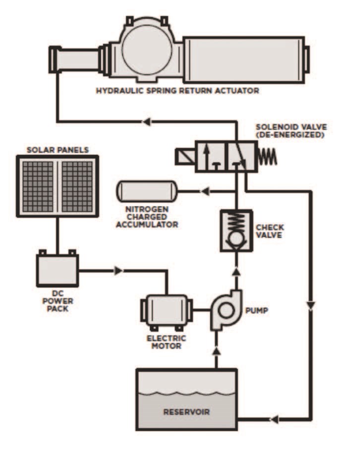
Without using pipeline gas, the energy needed to create hydraulic pressure in an electrohydraulic actuator can come from a variety of different electric voltage supplies based on site location. These include a direct electric supply, portable generator, and solar or wind charged battery power supplies.
Principal of Operation
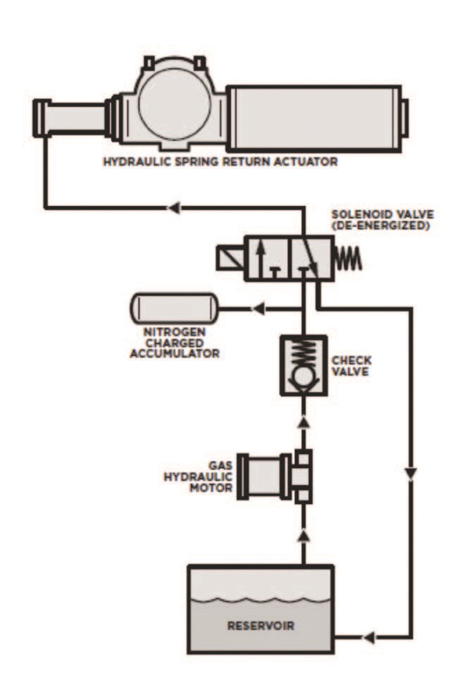
A double-acting hydraulic actuator uses fluid power pressure to drive the valve open or closed. A spring-return actuator uses fluid power pressure in one direction, but once the pressure is released, a mechanical spring drives the actuator in the reverse direction (known as the failsafe stroke).
The hydraulic pressure to run the actuator is readily available from the pump, a hydraulic accumulator, or a combination of both. If a stored energy accumulator is being used to maintain hydraulic pressure, the system will be monitored using a pressure switch, and the actuator controller will run the hydraulic pump to top off the system. Therefore, pressure is always available when either a double-acting or spring-return actuator is required to stroke the valve one or more times.
For very remote locations, the energy choices available to operate process equipment are very limited. In the case of valve actuators, rotational torque needs to be generated to open and close the valve while under pressure. This torque is generated by either a geared electric motor or a fluid source derived using a compressor or pump.
The most convenient method of powering remotely located devices is to use a reusable energy source to power a battery pack. The most efficient method of converting electric energy to rotary torque is the hydraulic powered actuator. Based on some of the following principals and criteria, one can produce enough torque to operate a large high pressure pipeline valve using a solar energy source. This removes the need for running electric power lines, or installing compressors or a centralized hydraulic power system — both of which require a heavy duty electrical supply.

Control Philosophy
For actuator sizing and selection, more than just the peak valve torque demand and safety factor need to be looked at. Other considerations include the valve stroke speed, and failsafe requirements on loss of power or control signal (fail open, fail close, or fail in position). These are key to the selecting the most efficient hydraulic actuator and pump combination.
In remote installations with limited available energy sources, energy conservation is critical. For example, Bray’s hydraulic actuators are engineered solutions for each application — to utilize available power options and select efficient energy storage — enabling multiple valve strokes without having to constantly run the hydraulic pump.
Line Break Operation
‘Line Break’ valves are required on federally regulated gas pipelines and are used to isolate a section of a pipeline upon leak detection. Line break actuators are controlled by pressure sensors located upstream and downstream of the valve. If a sudden rate of pressure change (indicating a pipeline leak) is detected, the leak will be isolated by closing in the surrounding valves. Following the remote shutdown event, a manual ‘reset’ of the actuator might be preferred before the reopening valve sequence commences (for instance, the actuator will not reopen unless a remote signal to open is present, and the local ‘reset’ button is pressed). The valve can also be opened and closed during normal operations through a separate dry contact initiation.
Since line break valves are normally open, there is a need to regularly exercise the valve, to ensure it has not become stuck in the open position. However, valve movement needs to be verified without shutting in the pipeline. This is done using a Partial Stroke Testing (PST) procedure.
Partial Stroke Testing
The PST control function partially closes a valve ensuring it is free to operate without stopping pipeline flow. Once movement has been detected the PST control returns the actuator to the fully open position.
Mechanical PST Device: A mechanical device is fitted to the valve (by a field operator) that restricts the valve movement to a small percentage of the total valve stroke. Once fitted, the field operator can radio the control room to operate the valve closed. Once normal movement has been detected, the PST is complete and the actuator can be returned to the fully open position and the mechanical device removed.
Electronic PST Method: Electronic PST testing is performed using a discrete PST signal to the actuator controller. Once the signal is received, the actuator will begin to close until a discrete PST limit switch is reached (at the nominated partial stroke limit). There is no need to have field operations present to instigate and witness this cycle test. However, some might still require this as an added precaution — or even initiating the electronic PST by pressing a local PST button on the actuator instead of using a remote signal. Electronic PST also times the partial stroke movement to make sure the valve is operating at normal speed, and it is not becoming slower due to a valve issue.
The electrohydraulic actuator is best suited for reliable safety related functions. The traditional gas-over-oil and direct gas actuators rely on conventional pneumatic controls, whereas the electrohydraulic actuator uses a state-of-the-art programmable PLC electronic controller. Safe operation is the highest priority for any mid-stream installation including transmission lines, metering stations, compressor or pumping station and product storage.
Safety Integrity Level
Recently, many industry sectors have adopted Safety Integrity Levels (SIL) to their critical safety control processes across their facilities. A SIL rating is a calculation on the possibility of a system failure. It is based on the safety rating of each system component, including the control system architecture. These factors all contribute towards a level of reliability and redundancy that will determine the SIL rating. Built-in capabilities, such as an electronic partial stroke testing (PST) capability, will increase the SIL rating of an automated valve package.
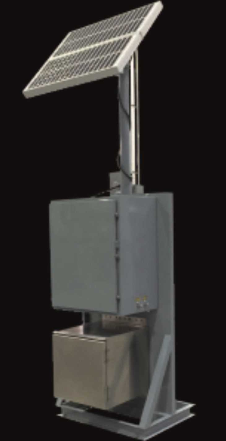
Zero Emissions: Green Energy Hydraulic Actuator
Principal of Operation: The electro-hydraulic actuator can use a solar powered battery pack to generate hydraulic pressure with a hydraulic pump motor. A stored energy accumulator can also be incorporated to minimize the load on the power pack by reducing the number of motor stops and starts to maintain hydraulic pressure at all times.
Conclusion
The electrohydraulic actuator is best suited for reliable safety related functions. Traditional gas-over-oil and direct-gas actuators often rely on conventional pneumatic controls, and will exhaust pipeline gas to the atmosphere. Self-contained electrohydraulic actuators use minimal or no pipeline gas to actuate the valve, depending on the method selected for pressurizing the hydraulic fluid. Safe operation is the highest priority for any midstream installation including transmission lines, metering stations, compressor or pumping stations, and product storage.
ABOUT THE AUTHOR

Howard Williams is Business Development Manager for Actuation & Controls at Bray International. With a degree in Marine Mechanical Engineering and an MBA, Howard has over 38 years in valve automation.