As oil and gas producers and processors announce ambitious plans to measure, reduce, and report emissions over the medium- and long-term, it is easy to overlook what immediate, cost-effective equipment changes and process improvement practices can be incorporated to achieve environmental, social, and governance (ESG) goals. These changes and improvements can also build stakeholder confidence with respect to the reporting of greenhouse gases (GHG), volatile organic compounds (VOC), and hazardous air pollutant emissions.
Emission Issues
One way to reduce incremental emissions is by reviewing practices and equipment for crude oil, condensates, and produced water storage tanks. Bulk liquid storage plays a critical role in the oil and gas value chain—but is also one of the largest sources of regulated air pollutants, including VOC emissions—as tanks experience flashing, working, and breathing losses through vents or vapor recovery systems.
Not surprisingly, over the last decade, most ESG goals have focused on measurement and reporting of VOCs (e.g., CH4, methane) emitted during flashing losses, with limited focus on emissions during working and breathing losses. Crude oil tanks emit methane and other light ends as crude oil pressure decreases from the
separator to the atmospheric conditions of the storage tank, this is the flashing process and it causes losses. Crude oil is stabilized after the initial flashing process and is unlikely to emit additional methane during its remaining time in the tank. However, it is possible for other air pollutants to be vented throughout the crude oil’s residence time in the tank.
Solution
Aligned with tank pressure control best practices, the following three critical actions can be taken to reduce incremental losses near the tank’s design pressure. Additionally, by answering each action’s key questions, tank farm managers can make progress toward reaching ESG goals:
1) Review design of vapor space pressure control devices.
• Are the correct valves, hatches, and vents with the tightest sealing technology installed on the tank? What is the estimated standard cubic feet per hour of emissions at 75% and 90% of setpoint?
• Are the valves and hatches optimally sized to prevent cycling and chattering?
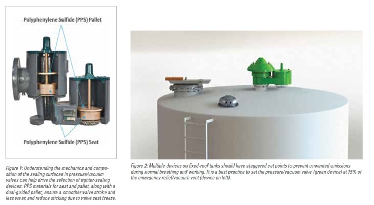
• Have the devices been tested and proven to exceed standard performance due to engineering improvements and material selection, such as the use of polyphenylene sulfide (PPS) seats? (Figure 1).
2) Ensure optimally staggered setpoints for vapor space pressure control devices.
• Are optimal layers of protection and emissions control achieved with the installed vapor space pressure control devices?
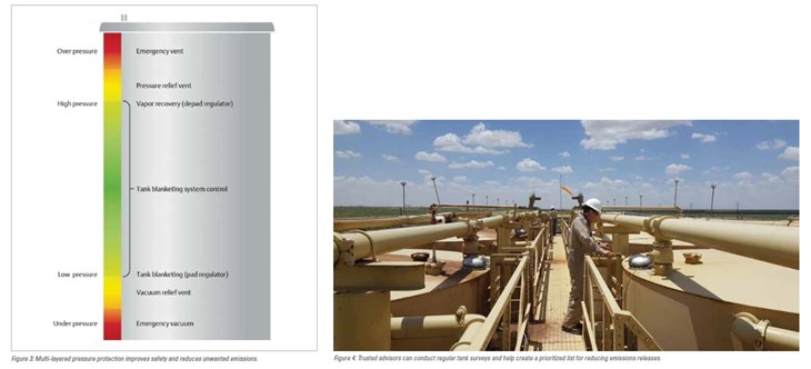
• Are setpoints set such that the desired capacity is achieved at a pressure that is 75% of the next device in the layer of protection spread?
3) Develop a detailed maintenance plan.
• Is device operation monitored?
• Are structured tank surveys conducted at a regular interval to maintain operational efficiencies?
• Are well pad or process conditions changes that can disrupt the tanks’ emission control devices tracked?
Upstream tanks are typically a fixed roof style, constructed from a cylindrical steel shell with a dome-shaped roof permanently affixed to the tank shell. The non-variable space within the tank drives the need for pressure/ vacuum control devices to release displaced vapors during changes in temperature (breathing loss) or liquid level (working loss), or during the flashing process.
These tanks also need a thief or gauge hatch for sampling, and should have an emergency vent to handle extreme overpressure and underpressure events (Figure 2). Furthermore, tanks should have a blanketing regulator to help maintain a consistant pressure when vapor recovery units are used. In aggregate, these vapor space over and under pressure control devices provide layers of protection to prevent tank rupture or implosion.
Pressure/vacuum control devices are usually set slightly above atmospheric pressure, and each should be sized to prevent the unecessary release of hazardous vapors during small changes in temperature (Figure 3).

Normal pressure changes occurring in a tank due to liquid level and temperature variations are managed by pressure vacuum vents, thief hatches, and tank blanketing and vapor recovery regulators. Emergency vents protect against abnormal pressure or vacuum that can occur due to a fire or system failure.
There is an implicit assumption that the materials and design of the breather valve will provide a tight seal until pressure rises to its set point. However, in practice, there is often leakage due to poorly designed gaskets and sealing surfaces, oversizing, and conflicting setpoints with the other layers of protection (i.e., thief hatch, emergency vent, or blanketing regulator). Ensuring hatch and valve products include enhanced sealing features can help reduce emissions by up to a factor of 10 when compared to traditional hatches and valves.
Additionally, over the course of normal operation, vapor space pressure control devices are susceptible to degraded performance caused by changing well conditions and wear. For example, a damaged seat on a
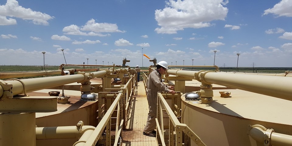
pressure/vacuum valve can cause excessive emissions if not addressed immediately. Regular tank surveys by tank farm managers or vendors can identify issues and inform a priority list for upgrading equipment to ensure reduced leakage rates (Figure 4).

Lastly, electronic monitoring of emergency vent, thief hatch, and pressure/vacuum valve operations can add an extra level of awareness and electronic documentation of when a hatch or vent might be stuck open and causing an unnecessary release. This option is particularly important to enhance personnel safety while working near tanks because it enables operators to prioritize tank maintenance walks through analysis of data collected from tank top devices.
Conclusion
Pollutant releases during tank breathing are likely under-reported to stakeholders because tank farm managers or reporting managers often assume pressure/vacuum control devices are designed and operating to best in-class standards. This oversight can be mitigated by developing a plan for investments to address the issues
discussed in this article. In turn, stakeholders can build confidence in the estimates provided in ESG reporting as companies move toward more responsible production practices.
As the oil and gas industry evolves, it is imperative to conduct due diligence of all potential emitting sources across the value chain. Reviewing the quality and installation of tank top devices is easily overlooked, but is a cost-effective way to prove to stakeholders that immediate actions are being taken to reduce VOCs and hazardous releases.
References
1. Air Permits Division. (2012). APDG 5942 – Calculating Volatile Organic Compounds (VOC) Flash Emissions from Crude Oil and Condensate Tanks at Oil and Gas Product Sites. Austin: Texas Commission on Environmental Quality.
2. American Petroleum Institute. (1998, April 01). Venting Atmospheric and Low-Pressure Storage
Tanks. Retrieved from API: https://law.resource.org/pub/us/cfr/ibr/002/api.2000.1998.pdf
3. Federal Energy Mangement Program. (2010). Operations & Maintenance Best Practices: A Guide to Achieving Operational Efficiency. Washington: U.S. Department of Energy.
4. Office of Air Quality Planning and Standards Emissions Factor and Inventory Group. (2006). Emissions Factor Documentation for AP-42 Section 7.1 – Organic Liquid Storage Tanks. Washington, D.C.: U.S. Environmental Protection Agency.
5. State of Colorado. (n.d.). 60.112a Standard for volitile organic compounds (VOC).
6. Texas Commission on Environmental Quality. (2012, May). APDG 5942 – Calculating Volatile Organic Compounds (VOC) Flash Emissions from Crude Oil and Condensate Tanks at Oil and Gas Production Sites. Retrieved from Texas Commission on Environmental Quality: https://www.tceqtexas.gov/assets/public/permitting/air/Guidance/NewSourceReview/guidance_flashemission.pdf
7. URS Corporation. (2009). Compendium of Greenhouse Gas Emissions Methodologies for the Oil and Natural Gas Industry. Washington, DC: America Petroleum Institute.
8. Wyoming Department of Environmental Quality. (2016). Oil and Gas Production Facilities Chapter 6, Section 2 Permitting Guidance. Cheyenne: Wyoming.
About the Author
Michelle Schulze is the pressure management industrial marketing manager for Emerson’s Automation Solution business. She focuses on developing integrated solutions to enable responsible energy creation and consumption, along with sustainable infrastructure development, across the globe. Schulze holds a Bachelor of Arts degree in economics from the University of Texas at Dallas, and an MBA from the University of Texas at Austin.


