

Background
Fugitive emissions represent a significant contribution to greenhouse gases, with atmospheric methane posing a particularly great risk due to its capacity to trap by volume 28 times more heat than carbon dioxide. Fugitive emissions from valves account for 60% of the total methane emissions from a refinery, with as much as 80% of the leakage, per valve, occurring at the valve stem .
The scope of this problem—valve leakage of fugitive emissions such as methane—is enormous. Consider that a single refinery has hundreds or even thousands of valves installed, often running 24 hours per day. Worldwide, the production and use of oil and gas is estimated to release 105 million metric tons of methane emissions, annually.
For these reasons, organizations like the Oil and Gas Climate Initiative (OGCI) have mobilized, with the backing of the world’s largest petroleum and natural gas producers, to focus on reducing upstream methane emissions. OGCI’s stated mission is to reduce the collective upstream methane emissions of participating organizations by more than 1/3, by a target date of 2025. This goal amounts to an annual reduction of 600,000 metric tons of fugitive methane emissions.
API 641 and ISO 15848 Standards
Today, there are several different standards for low emissions certification. This article will focus on the API 641 certification and the ISO 15848-1:2015 standard.
API 641 is specifically relevant to quarter-turn valves – the most common type of valve used in industry. The API 641 standard applies to all stem seal materials and dictates a stringent maximum allowable leakage of 100 parts per million by volume (ppmv). This API test standard calls for 610 mechanical cycles, as well as 3 thermal cycles to evaluate emissions performance over the expected five-year life of the valve. Under the Group A testing standards, temperatures are alternated between ambient temperature and 500 °F/260 °C, at increments of 100 open-close cycles of the valve, and pressure is constant at 600 psig. A static emissions measurement is taken before cycling begins, followed by 14 static leakage measurements and 7 dynamic leakage measurements throughout the testing procedure, as the temperature is raised and lowered.
For valves tested to API 641 that use a graphite-based packing material, the packing must first satisfy API 622. If
the packing set is not covered under the scope of API 622, the packing set does not need to be previously tested to API 622. This allows for the use of other packing materials, such as PTFE. Regardless of the packing material, no adjustment or re-torquing of the valve packing is allowed during the testing procedure for API 641.
ISO 15848-1:2015, ‘Industrial valves – Measurement, test and qualification procedures for fugitive emissions’,
addresses both isolation and control valves, and outlines testing procedures to measure leakage for the stem/shaft seals and body seals of the valve being tested. Under this specific standard, a control valve must be cycled from 40% open to 60% open, and there are distinct ratings for tightness class, endurance class, and temperature class.
The tightness class can be measured with helium or methane as the test fluid, the latter being more relevant to the topic of greenhouse gas emissions, and defines standards for the maximum allowable leakage at each class rating. The minimum tightness class of CM signifies allowable leakage of ≤ 500 ppmv, BM is for ≤ 100 ppmv, and AM is the world’s most stringent standard for methane leakage at ≤ 50 ppmv. It should be noted that these ratings apply specifically to leakage at the stem seals: leakage of methane at the body seals of a control valve must be ≤ 50 ppmv to achieve certification.
The endurance class ratings are broken out separately for isolation valves and control valves. An endurance class rating of CC1 signifies that a control valve has completed 20,000 cycles while successfully meeting at
least the minimum tightness class for allowable leakage. An endurance class rating of CC2 indicates that 60,000 cycles have been completed, and an endurance class of CC3 indicates that 100,000 cycles have been completed, again, while meeting at least the minimum tightness class standard for allowable leakage.
Finally, ISO 15848-1 also addresses temperature class ratings for fugitive emissions measurement, with the following designations: t – 196 °C (ranging from -196 °C up to RT), t – 46 °C (ranging from -46 °C up to RT), tRT (ranging from -29 °C up to + 40 °C), t200 °C (ranging from RT up to 200 °C), and t400 °C (ranging from RT up to 400 °C). As you can see, there is some overlap between the different temperature classes, with each range
having RT as either its maximum or minimum allowable temperature.
The Need for a New Control Valve Design
As mentioned above, valves are responsible for most of the fugitive methane emissions from any given refinery, with up to 80% of the emissions for any single valve leaking from the valve stem and diaphragm actuators that operate the valve. For the moment, we will put aside the matter of high-bleed methane actuators and focus on the design of the control valve itself.
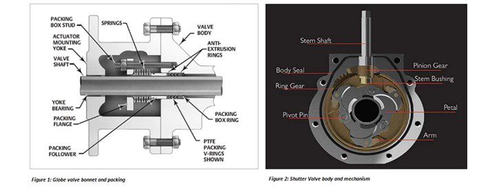
The globe valves commonly used in process control applications at the refinery tend to have multi-turn stems or linear moving stems that move up and down as they cycle from fully open to fully closed. For the packing to be effective, the packing box stud must be sufficiently torqued, compressing the flange, springs, and packing follower that subsequently compresses the packing itself to form a tight seal around the stem. The amount of
torque on the packing box stud is the key element to supply the necessary amount of loading on the packing.
Even when the packing is sufficiently loaded, the inherent geometric design of the globe valve bonnet and stem is relatively prone to leaks. Globe valves designated as “low emissions” by their manufacturer routinely emit 500 ppmv per valve, contributing to the annual tonnage of product lost into the atmosphere. The significant actuator torque required for operation, and the vertical movement of the valve stem are continuously
acting in opposition to the packing mechanism, which subsequently requires routine monitoring and adjustment in the field.
To mediate these issues, Clarke Valve designed and developed a control valve that is a departure in geometry
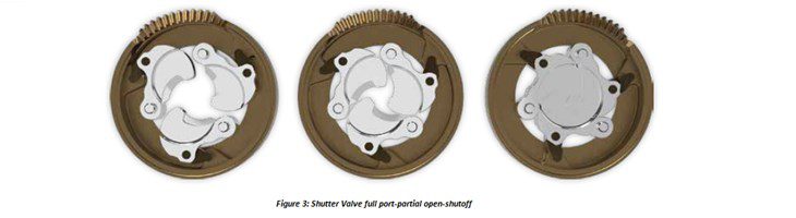
and functional operation from the globe valves currently in service worldwide. The Shutter Valve cycles from a tight shutoff to full port operation, using only a quarter-turn of the valve stem. A pinion gear and ring gear transform the rotary motion of the stem into the pivoting movement of three interlocking petals that control the aperture of the valve. This means that the stem does not perform any up and down motion, and requires significantly less rotation than the stem on a globe valve.
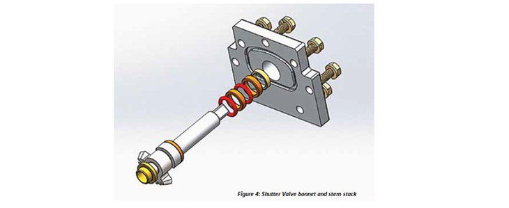
The bonnet of the valve also employs features that aid in pressure retention and helps eliminate any fugitive
emissions from the joints at the top of the valve. The loading is provided by the bonnet, which compresses a spring energized seal onto the packing rings. The spring energized seal effectively expands under pressure, and is located at the top of a stack of standard O-rings and PTFE bearings, around the valve stem. This mechanism
helps eliminates the need for packing studs and nuts, springs, followers, and any adjustment or re-application of torque in the field. An O-ring also seals the joints of the valve body and bonnet (Figure 4).
The valve can be operated with low torque, energy-efficient, electric actuators, eliminating the need for heavy,
high-torque, methane-bleed actuators that dump emissions into the atmosphere every time the valve is cycled. This is because the three interlocking petals open perpendicular to the flow of any process fluids, resulting
in a reduction of the fluid resistance to the valve opening or closing.
Conclusion
Owing to the valve’s design, it achieved both the API 641 certification for quarter-turn valves, and the ISO 15848-1:2015 certification for industrial control valves, during independent testing at Yarmouth Research and Technology, LLC. In the case of API 641 testing, the valve produced average emissions of 6.25 ppmv, easily surpassing the standard of 100 ppmv. For ISO 15848-1, the valve consistently, allowed less than 10 ppmv over the course of 100,000 mechanical cycles.
Valve design performance metrics like these have recently caught the attention of organizations like OGCI, and
led to the $5.5MM USD investment by OGCI in Clarke Valve’s emissions reduction technology in 2018. New
valve designs can reduce the per valve emission of methane by as much as 95%. As oil and gas producers begin to increase the adoption rate of new technologies to replace the millions of globe valves currently in service, it will accelerate the timeline to reach the ambitious fugitive emissions reduction goals established by OGCI and others.
About the Authors
Kyle Daniels, President and CEO, Clarke Valve.
Kyle Daniels is an aerospace engineer and the inventor, chief engineer and head of product design of the Shutter Valve. He holds several patents on the Shutter Valve and is an expert in the field of industrial valves. Mr. Daniels spent his career in the aerospace industry working at
Kyle Daniels is an aerospace engineer and the inventor, chief engineer and head of product design of the Shutter Valve. He holds several patents on the Shutter Valve and is an expert in the field of industrial valves. Mr. Daniels spent his career in the aerospace industry working at
General Electric, Pratt & Whitney, and Embraer Aircraft. He is a graduate of The Ohio State University’s prestigious Aeronautical and Astronautical Engineering program, and also received a master’s degree (magna cum laude) from Brown University’s Program in Innovation Management and Entrepreneurship. Mr. Daniels is from Miami, FL and has resided in Ohio, Connecticut, Rhode Island and Paris, France.
Catherine LeBoeuf, Lead Fluid Dynamics Engineer.
Catherine LeBoeuf is responsible for the Advanced Technology department at Clarke Valve™ and has worked on the development and optimization of new and innovative control valve technology during her time with the organization. Catherine manages all computational fluid dynamics (CFD) simulations for Clarke Valve’s R&D efforts and for customer implementations. She holds a Bachelor of Science degree in Engineering from Brown University with a concentration in Materials Engineering.