As mentioned in Part One, there are many other less common valve designs that can be encountered in the field when performing LDAR monitoring that might warrant special consideration such as rising stem ball valves, pipeline valves, or valves with auxiliary connections. Valves with a thermal relief system with an optional manual body bleed, for example, would be considered an Open-Ended Line (OEL), unless this bleeder is either cap/plugged or routed back into process. Examples of these types of valves and the monitoring locations per M21 or HJ733 are depicted in Images 8 and 9.
Another less common type of valve is a piston type sampling valve. Sampling valves are used to withdraw a live sample from a process. The most common application in refineries is sample taps on the sides of storage tanks. The hand wheel needs roughly 8 full rotations to pull the internal plunger back far enough to allow process to flow out the angled exit port. When sampling is completed, the plunger pushes the left-over process material back into the line, thus when next used the first drop captured will be representative of current operations. These purge-less sampling valves meet the requirements for sample system flushing
control per USPEA requirements but need to be plugged or double blocked to meet USEPA OEL requirements. When monitoring a piston type sampling valve, the following areas should be monitored per M21 or HJ733 (Image 10).
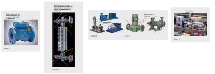
In the field there are many valve types that are not treated as a monitoring requirement under U.S. EPA LDAR regulations. Check valves are designed to prevent back flow within a process line and are often self-acting with no external input required thus there is no stem seal or potential leak path. Considering this, most LDAR programs treat check valves as connectors. Those that include check valves under a valve classification, normally include them as No Detectable Emissions (NDE), which is less than or equal to 500 ppmv, requiring M21 or HJ733 only on an annual basis. When monitoring a check valve, the following areas should be monitored per M21 or HJ733 (Image 11).

Sight Glass valves which are often found at the top and bottom of the level gauge. Sight glass valves provide a visual indicator of the current fluid level. Several different configurations of this type of valve can be used. One common configuration is a three-port two-way valve that in one position opens the vessel to the sight glass and in the other position opens the sight glass to a vent or bleed. Others can have a ball check on the vessel side, isolating the sight glass allowing it to be drained and cleaned. Sight glass valves typically have a union packing nut, and a union bonnet for mounting. It can be difficult to decide if these unions are bonnets or mounting connectors. With the variation it is also difficult to determine whether a second block valve is enough to comply with the OEL requirements. When monitoring a sight glass valve, the following areas should be monitored per M21 or HJ733 (Image 12).
While discussing all the components used to regulate flow, it is important to understand exactly where this flow comes from within the facility. Pumps and compressors create high pressure which allows process flow within the units or tanks. Pumps in general move liquids, while compressors generally move gases. With these potentially high pressures sealing becomes quite complicated. The shaft seal is the primary leak point, but all other items penetrating the body of the pump or compressor must be monitored per USPEA requirements. When monitoring a pump, the following areas should be monitored per M21 or HJ733 (Images 13 and 14).
The same as pumps, compressors can be either centrifugal or reciprocating. Compressor seals are designed to limit leak, not prevent leakage. Most LDAR requirements specify engineering controls for compressors rather than just M21 or HJ733. Compressors are large and complex, with many potential leak points, which makes them very complicated to monitor correctly. When monitoring, focus on the shaft seals or the enclosure around it and any penetrations of the compressor body. Reciprocal compressors can have cylinder loading or unloading valves that are considered part of the compressor because they are embedded in the compressor cylinders and not on piping from the compressor. When monitoring a compressor, the following areas should be monitored per M21 or HJ733 (Image 15).

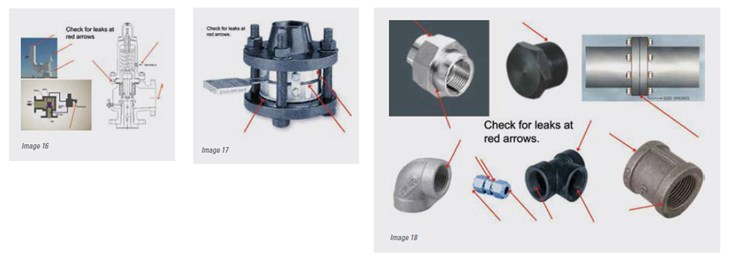
Pressure Relief Devices (PRDs) which include Pressure Relief Valves (PRVs), Pressure Safety Valves (PSVs) and Rupture Disks (RD) are all exempt from the USPEA OEL requirements, as it would be too dangerous to plug them off. PRDs in gas vapor service are required to meet the USPEA NDE requirements and if a relief does take place the PRD must be monitored after the release is completed to show that it has reseated properly meeting the USPEA NDE requirements once again. RDs are a solid plate which is designed to rupture at a set design pressure. RDs are normally only used on batch processes, as once they rupture a shut-down of the process unit is required for replacement. When monitoring a PRD or Rupture Disk, the following areas should be monitored per M21 or HJ733 (Images 16 and 17).
Components types that vary the greatest are connectors. Within LDAR programs connectors include; flanges, unions, threaded fittings, compression fittings and welds. Some regulations require connector monitoring, but most just require emission estimating for their EI. Flanges are normally found in larger and higher-pressure lines. A flange is attached to the pipe so that two sections can be bolted together with a gasket in-between to prevent leakage. This design allows the facility to remove sections of pipe without having to cut. Unions are made up of male and female pieces, which can each be attached to and end of pipe, thus pulling it together in the process of tightening. Threaded fittings are usually limited to smaller piping and include; elbows, plug, caps and bushings. Tubing components are generally compression fittings which can perform well even at high pressures. Welds within a facility are exempt from M21, but with newer technologies like the IR camera some welds have been found to be leaking. These leaks though would still not be considered a LDAR leak within the USEPA requirements. When monitoring a connector, the following areas should be monitored per M21 or HJ733.
With so many different types of components existing within a facility, the knowledge required to properly monitor per M21 or HJ733 is significant. Without this knowledge, even with the advancements of seal technology and the development of qualification test such as API 624, API 622 and API 641true fugitive emission reduction might never be seen. Until all of the components within a facility are truly upgraded to new CLLT components and LDAR technicians understand every component and the place in which they must monitor, opportunities for emissions reductions will be missed. With proper training and understanding of each component type users can maximize the effectiveness of LDAR programs. Hopefully future technologies will come to the forefront which allow M21 to be completed on an annual basis for valves and monthly for pumps, but in the meantime knowledge is the key to success.

About the Authors
Bronson Pate is the Global Vice President for RFS Compliance Solutions. Growing up in this industry has given him a well-rounded and diverse 33 years of experience. The last 10 years were professionally focused on international commerce, development of Leak Detection and Repair (LDAR) programs, thus leaving him with a stellar track record of helping clients achieving compliance pertaining to the Clean Air Act enforced by the United States Environmental Protection Agency. He has performed 250+ USA Consent Decree LDAR audits with many more on the horizon.
Sam Davis is the founder and President of RFS Compliance Solutions. With over a decade of experience, Sam contributes his passion and knowledge for the industry, on being born and raised in it. After 9 years of working for Beric Valves, as the Director of Global Business Development, Sam has branched off to start his own company, Refining Focused Services (RFS) Compliance Solutions. This allows him to work side-by-side with the industry to achieve leading environmental compliance through consulting and technology. When not in the field, Sam is spending his time sitting on global panels providing content and contacts for future environmental conferences.
Check out Part One in the September 2019 issue of Fugitive Emissions Journal, or view it online here: http://bit.ly/2HcVLNG.


