As a growing number of oil & gas facilities worldwide implement leak detection and repair (LDAR) plans, owners and the public are interested to understand better their effectiveness, and how total facility leak emission is decreased as a result of LDAR implementation. For this objective, it is critically important when calculating total mass leak emission to consider an estimated leak lifetime for the leakers found. More frequent monitoring and shorter leak repair time should return less leak lifetime and less emission. This simple yet important factor is mentioned but not detailed in existing guides. Some guides are suggesting formulae with the same equipment operating time both for leakers and non-leakers, which is not quite accurate since the actual leak lifetime could be significantly less than the total equipment operating time due to the proper LDAR implementation. In this article, the authors are addressing this gap. The LDAR efficiency evaluation approach utilizing leak lifetime is suggested and illustrated by samples.
By Eugene Kolonsky, Ph.D.a, Semen Neverovb, and Johan Wictorc, Pergam
Background
Leak detection and repair (LDAR) plans are widely recognized as an approach to control and reduce fugitive leaks of pollutants and greenhouse gases in oil, gas, and chemical facilities. The requirement to implement LDAR plans is included in the global Methane Guiding Principles1, supported by all industry majors. The U.S. Environmental Protection Agency (US EPA) published the Best Practice Guide2 for voluntary LDAR implementation. The American Petroleum Institute (API) published a comprehensive Compendium3 for the total equipment leak quantification methods. The United Nations (UN) Oil & Gas Methane Partnership (OGMP) publishes the Framework for emission reporting and Technical Guidance Documents (TGDs), including TGD for unintended equipment leaks4. The UN program “Clean Development Mechanism” allows under certain conditions5 recognize leak emissions decrease as Certified Emission Reductions (CERs), or carbon credits, which can be later traded on marketplaces.
The nature of equipment leaks is that they are usually unintentional, small, hard to detect, and may exist for a long time. An unintentional leak might happen at any time due to wear and tear on any equipment connection, such as flanges, valves, pumps and more, all named ‘components’. There are dozens of thousands of such components in the average facility. If not found and repaired, unintentional equipment leaks could essentially contribute to the total facility emissions when combined with process vents and flares.
LDAR efficiency is defined as an absolute and relative fugitive emissions reduction due to LDAR implementation. According to Texas Commission on Environment Quality (TCEQ)6, the LDAR efficiency varies from 30% to 97% depending on LDAR frequency, leak definition threshold and repair requirements. The baseline equipment leak emission found with use of average EFs approach (API Compendium3), and actual equipment leak emissions, found with use of actual LDAR monitoring data, should be calculated, and compared to evaluate LDAR efficiency.
In this article the authors suggest an approach for actual leak emission calculation utilizing a leak lifetime time basis for a more accurate LDAR efficiency evaluation.
The following is a step-by-step approach. The sample calculations are inspired by API Compendium3 Exibits. For clarity purposes the following assumptions are made:
onshore gas production facility is considered,
methane (CH4) emission is calculated,
LDAR monitoring is implemented using Optical Gas Imaging (OGI) cameras with leak sensitivity 60 g/hr.
- Baseline Emission
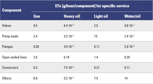
1.1 Baseline Emission Factors
Emission factors depend on component and service type and are defined by Table 1.
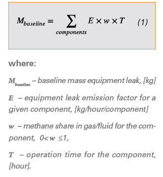
Baseline emission is calculated with the following formula:
1.2 Sample Calculation
INPUT DATA
There are 100 gas valves, and 250 flanges in a stream at a gas production site that contains 80 percent methane by weight. Calculate the methane emissions in a year.
CALCULATION METHODOLOGY:
Emission is calculated using EFs from Table 1 with formula (1).


2. Actual Emission
2.1 Leak Lifetime Definition
Leak lifetime Tleak is a sum of awareness time TA from leak appearance to leak detection and repair time TR from leak detection to leak repair:

An unintentional leak may appear at any time. According to OGMP recommendations (API Compendium 20214, 7.1.5 “Time Basis of Equipment Leaks”) suggested:

Slightly more sophisticated cases for leak lifetime estimation are considered in OGMP TGD-2 “Unintended equipment leaks”4, Section “Leak duration”.
2.2 Actual Emission Factors for Monitoring with OGI Cameras
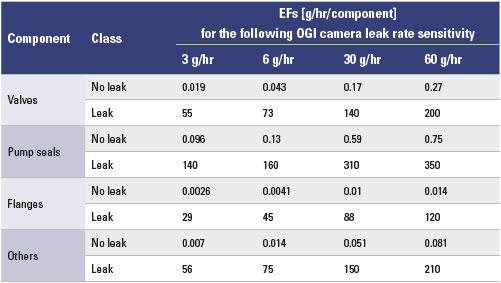
Optical gas imaging (OGI) cameras can detect a leak and help to localize the leak source, but still cannot reliably measure the leak rate. As a result of facility monitoring with OGI cameras, all components population is divided into two classes: class ‘no-leak’ with the majority of components, where leaks were not detected by the monitoring tool, and the minority class ‘leak’, where the leaking components were detected. For this kind of monitoring a special approach to total facility mass emission quantification was developed, called ‘leak/no-leak approach’, or ‘screen range approach’, and EFs for class ‘leak’ and ‘no-leak’ were derived3. It should be noted that EFs for the ‘no-leak’ class are not equal to zero, though very small. This way the ‘leak/ no-leak’ approach acknowledges the fact that small leaks still may exist below the threshold of the instrument sensitivity. The EFs for monitoring with OGI cameras depend on the OGI leak rate sensitivity and are shown in Table 2.
OGI camera leak rate sensitivity is given by the camera manufacturer or may be found experimentally. US EPA recommends using a conservative threshold of 60 g/hr7. Note that EFs in Table 2 do not depend on the service type.
The actual emission is expressed using the formula:
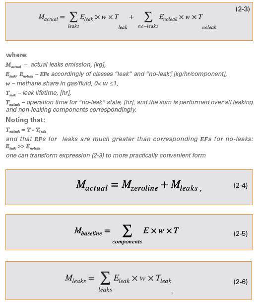
Emission volume Mzeroline can be thought of as the lowest achievable equipment leak emission level for a given facility and a given leak threshold definition. If no leaks are found on a facility at LDAR monitoring phase, the actual emission is as low as Mzeroline. This way the method takes into account the scale of components population on the facility and admits the fact that some leaks still may exist below the leak definition threshold.
2.3 Sample Calculation
INPUT DATA:
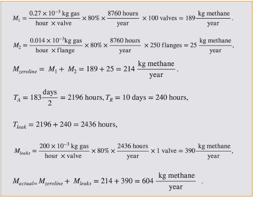
On the same site as described in the Sample 1.2 above with 100 gas valves and 250 flanges, regular LDAR monitoring with OGI cameras is performed. The reporting period is one year. At the first observation performed on the 1st of April, no leaking components were detected. At the second observation performed on the 1st of October one leaking valve was detected. The leak was repaired in 10 days. Calculate the actual methane emissions and compare them with the emissions baseline from Sample 1.2.
CALCULATION METHODOLOGY:
Emission is calculated using EFs from Table 2 with formulae (2-4, 2-5, 2-6) for mass emission calculation and (2-1, 2-2) for leak lifetime.
3. LDAR Efficiency
3.1 Efficiency Definition
As mentioned previously, LDAR efficiency is defined in terms of relative emission reduction:

It should be noted here that the actual emission Mactual does not have to be less than the baseline emission Mbaseline. It might happen that the actual emission appeared to be greater than the baseline, especially at the first cycles of LDAR monitoring, when a lot of hidden leaks may be found. From the formal point of view at this moment the LDAR efficiency will be negative. This should not be taken as the reason to stop the LDAR implementation. In a few LDAR cycles, most of the leaks will be repaired and the actual efficiency will stabilize essentially below the baseline, according to TCEQ.6
3.2 Sample Calculation
For known Mbaseline and Mactual, the LDAR efficiency is found with formula (3-1):

Conclusion
In this article a simple approach to LDAR efficiency evaluation is suggested. The approach is illustrated by samples for LDAR OGI monitoring on onshore facilities, but it can also be applied to other types of monitoring and facilities. Owners and operators using this approach can better understand and correlate the influence of monitoring frequency, repair time and other factors, such as definition threshold, on overall LDAR efficiency. Therefore, operators and owners can achieve better results on LDAR costs.


References:
- UN CCAC, “Methane Guiding Principles,” 2017.
- EPA, “Leak Detection and Repair. A best practices guide.,” 2007.
- API, “Compendium Of Greenhouse Gas Emissions Methodologies For The Natural Gas And Oil Industry,” 2021.
- OGMP 2.0, “Technical Guidance Document Number 2 (TGD-2) “Unintended Equipment Leaks”,” 2021.
- UN FCCC, “Approved baseline and monitoring methodology AM0023 “Leak detection and repair in gas production, processing, transmission, storage and distribution”,2021.
- Texas Commission on Environmental Quality (TCEQ), “Air Permit Technical Guidance for Chemical Sources. Fugitive Guidance APDG 6422.,” 2018.
- EPA, “Subpart W. GHG Emission reporting. Background Technical Support Document.,” 2015.


