


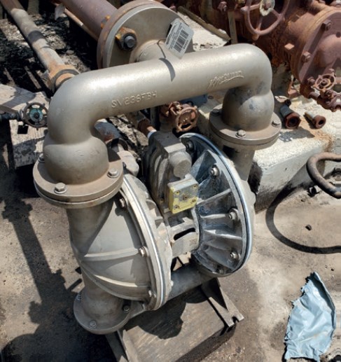
8.3.1.3 – Pumps and Compressors.
Conduct a circumferential traverse at the outer surface of the pump or compressor shaft and seal interface. If the source is a rotating shaft, position the probe inlet within 1 cm of the shaftseal interface for the survey. If the housing configuration prevents a complete traverse of the shaft periphery, sample all accessible portions. Sample all other joints on the pump or compressor housing where leakage could occur.

Section 8.3.1.4 – Pressure Relief Devices
For Pressure Relief devices that vent into the atmosphere, as shown in Figure 9, the probe tip should be placed at the center of the ‘horn.’ If the ‘horn’ is out of reach, the ‘weep’ hole (noted by the green arrow in Figure 9) is the best alternate. 8.3.1.4 provides a little more detail on interfaces, but overall, these two locations are going to be the main areas to review.

8.3.1.4 – Pressure Relief Devices.
The configuration of most pressure relief devices prevents sampling at the sealing seat interface. For those devices equipped with an enclosed extension, or horn, place the probe inlet at approximately the center of the exhaust area to the atmosphere.
Section 8.3.1.5 – Process Drains
For Process drains, the monitoring location is at the center of the opening to the atmosphere. If the drain is covered then it is important to monitor the circumference of the drain covering.

8.3.1.5 – Process Drains.
For open drains, place the probe inlet at approximately the center of the area open to the atmosphere. For covered drains, place the probe at the surface of the cover interface and conduct a peripheral traverse.
Section 8.3.1.6 Open-ended Lines or Valves
For open-ended lines or valves in 8.3.1.6, the probe tip should be placed in the center of the opened area. Do not pass the plane of the opened area though when monitoring.
8.3.1.6 Open-ended Lines or Valves.
Place the probe inlet at approximately the center of the opening to the atmosphere.

Section 8.3.3.1 and 8.3.3.2 – Alternate Screening Procedure
For alternate methods of testing refer to sections 8.3.3 of Method 21. This section provides insight into the soap solution method which uses the appearance of bubbles as the solution is placed onto the component to indicate a leak. While this method is not used in a day-to-day LDAR world, it is used by maintenance and operations personnel if a re-monitoring technician is not available.
8.3.3.1 A screening procedure based on the formation of bubbles in a soap solution that is sprayed on a potential leak source may be used for those sources that do not have continuously moving parts, that do not have surface temperatures greater than the boiling point or less than the freezing point of the soap solution, that do not have open areas to the atmosphere that the soap solution cannot bridge, or that do not exhibit evidence of liquid leakage. Sources that have these conditions present must be surveyed using the instrument technique of section 8.3.1 or 8.3.2
8.3.3.2 Spray a soap solution over all potential leak sources. The soap solution may be a commercially available leak detection solution or may be prepared using concentrated detergent and water. A pressure sprayer or squeeze bottle may be used to dispense the solution. Observe the potential leak sites to determine if any bubbles are formed. If no bubbles are observed, the source is presumed to have no detectable emissions or leaks as applicable. If any bubbles are observed, the instrument techniques of Section 8.3.1 or 8.3.2 shall be used to determine if a leak exists, or if the source has detectable emissions, as applicable.
Final Thoughts
As can be seen, each component has its own specific section written into how to properly monitor it, per Method 21. Although this test method is very detailed in explaining how to monitor each interface, leaks are still getting missed. So why is that? Truly it is all about the speed, angle of the probe to the leaking interface, and making sure that the probe is truly on the leaking interface. By understanding the test methods, and specifically the monitoring locations, an operator or monitor will be able to more effectively find and address the present leaks.
With a more comprehensive understanding of Method 21, the addition of Certified Low Leaking Technology, and the advancements of the standards associated with API 622, API 624, API 641, ASME 16.20, and ISO 15848, individuals will be better able to achieve a true reduction in emissions.
About the Author
Bronson Pate is a Client Relationship Manager with TRICORD Consulting, LLC. Bronson is an LDAR Subject Matter Expert with more than thirteen years of professional experience within the industry. He has participated in and/or led over 275 third party LDAR audits and has worked with multiple facilities to develop LDAR programs both domestically and internationally.