

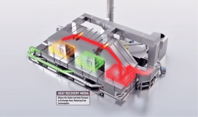
Gas Flares are extremely inefficient, as well as problematic in guaranteeing a consistent Destruction Removal Efficiency (DRE). While Direct Fired Thermal Oxidizers (DFTO), also known as Afterburners, have been the most common air pollution control device installed to replace flares, there are applications in which the use of a Regenerative Thermal Oxidizer (RTO) has proven to be a more effective and efficient solution.
The following case studies, one from a Liquid Chemical Terminal and another from a Midstream Gathering Station, both demonstrate the benefits of utilizing an RTO as opposed to DFTO when replacing Flare technology, as they can minimize fuel consumption while better handling variable fluctuations and higher loading for a maximum DRE of Emissions.
A large industrial chemical distributor was expanding their tank loading/ unloading terminal operation and required a new capture and control system for fugitive emissions to keep the facility compliant with stricter environmental regulations. In addition, safety was also of major concern as these Terminals are prone to a large number of explosions and accidents due to burst of high exothermic releases within the system. Tank loading/unloading terminals serve as a vital liaison between chemical producers and transporters and consist of chemicals or petroleum storage tanks and loading/ unloading racks for truck delivery of bulk chemicals to satisfy local demands. While storage tanks generate emissions during idle times when there is no activity, significantly greater amounts are released while material is actively being loaded or unloaded out of the tank.
The fluid movement and turbulence effect during this transfer process generates excessive airborne vapors which are collected at the top of the tank. The amount of vapor generated in the tanks also depends on available vapor space in the tank, as well as temperature variation and vapor pressure inside the tank.
Due to increasingly stringent EPA emissions requirements, tank terminals must utilize vapor collections and emission control technologies at all times. The most common pollution controls solution installed for the application consist of discrete individual vapor collection systems attached to a single common emission control equipment such as a flare, or Direct Fired Thermal Oxidizer (DFTO).
However, the disadvantage of a flare or DFTO is the high fuel and operational cost associated with continuous use. During the active loading/unloading periods, the emission control equipment burner does not need to draw on the assist fuel gas (i.e. natural gas), however, excessive fuel is required to operate the emissions control equipment during idle mode, as significantly lower hydrocarbon concentrations are released from tank standing losses.
When designing the new air pollution control system, the primary focus was on optimizing energy efficiency and fuel savings, as well as operational safety. The best solution to handle the large fluctuations of incoming vapors with varying concentrations of hydrocarbons across the entire terminal operation, was a central vapor collection tank to capture the emissions from the various loading and unloading racks and container filling stations. The vapor collection tank, also known as a bladder tank, consisted of a floating bladder mechanism incorporated with different position level sensors and pressure measurement instrumentation for effective monitoring over vapor collection.
In addition, a series of automated sensors were placed between the vapor collection tank and RTO, regulating the subsequent release of vapors into the emission control system. Depending on the loading and unloading activity and rates, the collection tank offered the new capability to hold vapors ranging from 4 to 7 hours before releasing into the Thermal Oxidizer system.
This allowed the RTO to remain in idle mode until the collection tank reached the preset discharge collection levels, which subsequently triggered the RTO to heat up to its operating temperature of 1,400 °F in preparation for the full collection tank to divert the vapor towards the oxidizer unit. An inlet flow control mechanism was utilized to control high concentration overloading into the RTO by managing inlet vapor flow rates and mitigated excess vapor from accumulating in the collection tank. A key advantage of this automated integrated system was that it minimized the required capacity of the Thermal Oxidizer system, as well as use of fuel during idle times, allowing for a more efficient design.
Since an array of volatile emissions were present across the station, several safety features were incorporated into the design to mitigate any fire and explosion concerns and trigger a system shutdown in the event of excessive hydrocarbon concentrations being diverted to the Oxidizer.
Custom specialized lower flammability limit (LFL) monitors were utilized throughout the system to measure flammability levels in the incoming vapors and provide feedback signals to control dilution air volumes. As an added precaution, a series of blocking valves and temperature monitoring controls were utilized across the design to react in the event of any system malfunctioning, and flashback dangers. The Thermal Oxidizer system design also incorporated flame arrestors to address any potential concerns of flashbacks to the vapor collection tank.
The integrated approach of combining a vapor collection unit with the Thermal Oxidizer system resulted in significant capital cost savings to the chemical distributor, up to 50 %, in comparison to conventional approaches.
In addition, they system achieved a higher destruction rate efficiency (DRE) up to 99.99% during the regulatory compliance testing phase. The solution also offered lower ongoing operating cost for emission control system by maintaining the Thermal Oxidizer in idle mode, with the exception of the vapor collection tank discharge periods.
CASE STUDY 2: Dual RTO System Replaces Open Flare for Major Midstream Operation
A leading Midstream company needed new equipment to achieve a higher DRE and treat the H2S (sour gas) from their process. In the past they had utilized a Flare; however, it failed to achieve the DRE needed to remain compliant with emission regulations.
In general, the midstream gas business starts at the gathering system, collecting wet natural gas from various well heads and transporting it to a single gas processing plant. At the gas processing plant, methane (a.k.a. dry natural gas) is separated from the wet natural gas, leaving heavier natural gas liquids (NGLs) including ethane, propane, butane, isobutane, and other condensates, as by-products. The midstream company then fractionate, transport and market these natural gas liquids.
Fugitive emissions were already of great concern as this gathering system consisted of thousands of miles of small-diameter, low pressure pipes collecting from hundreds of wells.
However, the Flare replacement remained the central issue. After the engineering team at Epcon analyzed the process and discussed various technologies, the final decision was on two large capacity 50,000 SCFM Regenerative Thermal Oxidizers (RTO). The dual oxidation system had the ability to automatically detect and increase oxidation efforts when the high-concentration vapors were introduced. The RTO technology also achieves a much higher DRE than the previously utilized Flare, up to 99.9% of VOCs, while also treating the H2S (sour gas) present in the process. The new RTO air pollution control system not only had better fuel consumption compared to the Flare, but was also able to handle the variable fluctuation and higher loading.
Conclusion
Both Liquid Chemical Terminals and Midstream Gathering Stations must continuously meet strict emissions guidelines while managing various flows of a broad range of chemicals and associated vapor streams with large fluctuations in volume and VOC content. In applications such as these, an RTO with comprehensive system controls, achieves better fuel consumption as wells as higher DRE levels, up to 99.9%, in comparison to Flare or DFTOs. Both these cases outline how the RTO, when custom engineered into the overall system, proved to be operationally more efficient, saving on excessive fuel combustion, and a greener solution for the environment and the customers.
About the Author
Tasha Jamaluddin is Managing Director of Epcon Industrial Systems, LP, widely published with technical expertise across industrial applications. She is a graduate of Harvard Business School (OPM Class 51) with a Master’s Degree from NYU, a certified LEED, AP with the US Green Building Council , and OSHA 30 Certified in General Industry Safety. She is currently serving her 3rd charter for the Environmental Technology Trade Advisory Committee (ETTAC) to the US Department of Commerce as Chair of the Climate Change Mitigation and Resilience Subcommittee.